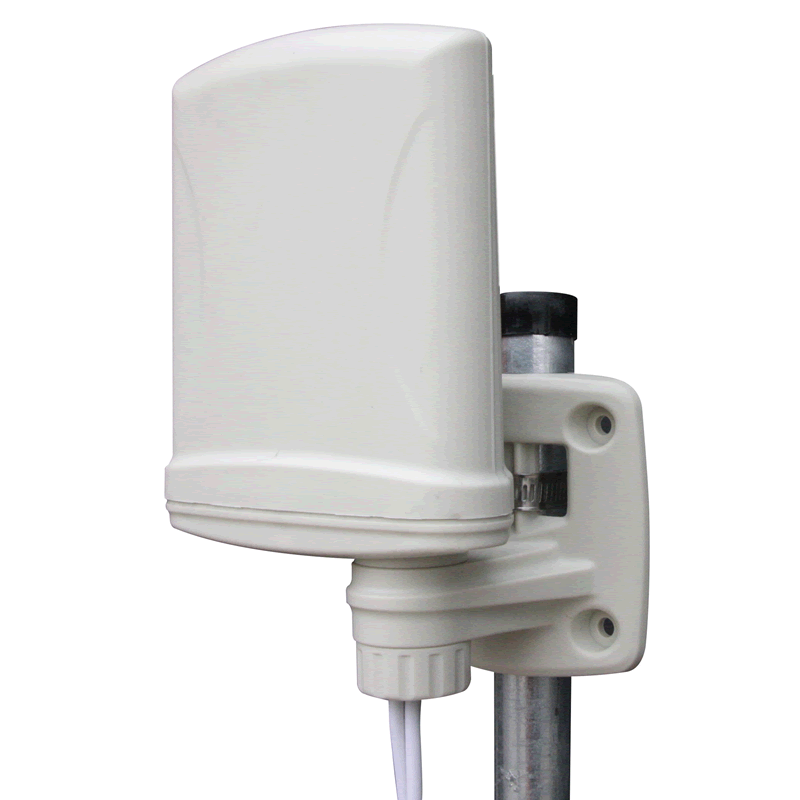
Indoor solutions required? First, to analyze whether the macro cell coverage is enough. Even if the macro analysis of the project and the macro network test-drive network has sufficient coverage, additional site survey should confirm that all the target areas are covered and, more importantly, the fact that the dominant server can be found in all areas. If this latter condition is not fulfilled, the internal systems may be required in addition to adjusting the macro network.

Second, estimate the capacity requirement for a particular model of traffic and number of users. As this process begins with macronetwork, use the normal amount of macronetwork. If the first two stages of the analysis show that the solution must be closed, to determine the correct radio antenna system. This depends on the status of any existing system:
•The existing system has an antenna : Implementation Additional studies and analysis of the site to ensure that the number of internal antennas and their separation is sufficient to 3G technology operating in 2.1 GHz band. Indoor systems for 2G technology may not be compatible with only the lower frequency bands, namely 900 and 1800 MGts.
This projects should take into account the significant differences in path loss, especially in passive systems have been deployed to cater to GSM900. when active systems are available, the main focus should be on compatibility with existing equipment of a higher frequency range. In any case, make sure that the resulting distribution of the antenna is compatible with the design of the target.
•No existing equipment or existing equipment is not compatible: Plan a new antenna system.
- If the room is small, consider passive DAS. Radio signals can come from a picocell or standalone repeater, depending on the expected traffic covered.
- If the room is large, consider active DAS. Radio signals received from the picocell due to the huge size of the area to be covered and the expected traffic (e.g.> 200 internal antenna feed length, a large area, a large separation smokers etc.).
- Use the leaky coaxial cable in the subway tunnels, underground areas and walkways, or where users and coaxial and are in the nature of the solution makes it leaky coaxial attractive.
It can be used in areas where DAS antenna is impractical or unsuitable, for example, subway tunnels, wherein a low-profile antenna to avoid physical interference with the passing train. The design of the radiating coaxial cable provides uniform coverage throughout the tunnel, which is an effective solution to overcome the radio dead spots. Leaky coaxial may be used in conjunction with ATM or repeater systems to increase system capacity (or tunnel) coating.
Assuming that the DAS required link budget can be used to determine which MAPL include both gain antennas / loss, and propagation loss. The antenna system gains / losses are directly related to the hardware used, while the propagation loss, depending on the model of distribution and any of the available fields. To solve the first point on, all the common internal network elements (carrier combiner couplers, couplers, antenna) to be used in the analysis were identified and listed. The exact position of antennas and feeder lengths are not needed at this stage. The main objective is to determine the appropriate radio and antenna system solutions.