Lte network architecture (lte network components, lte architecture)
The Long-Term Evolution (LTE) network architecture is a crucial component of modern wireless communication systems. In this overview, we will delve into the key aspects of LTE network architecture, including its structure, nodes, and functionalities.
ENodeB: The Radio Access Node
At the heart of the LTE network is the ENodeB (eNB), which serves as the radio access node. This node is responsible for a multitude of functions, making it a critical component of LTE communication.
Radio Access and Control
The primary responsibility of the ENodeB is to handle all radio access and control functions. This includes:
- Radio Resource Management (RRM): ENodeB manages radio resources efficiently, ensuring optimal connectivity and bandwidth allocation to User Equipment (UE).
- Radio Bearers: It establishes and maintains radio bearers, which are logical channels for communication between the UE and the ENodeB.
- Mobility Management: ENodeB manages handovers and mobility of UEs within its coverage area, ensuring seamless connectivity even during movement.
Evolved Packet Core (EPC): The Core Network
While the ENodeB deals with the radio access, the core network, known as the Evolved Packet Core (EPC), handles the core functionalities of LTE.
Mobility Management Entity (MME)
The equivalent of the UMTS SGSN in LTE is the Mobility Management Entity (MME). MME is a crucial element in LTE network architecture responsible for control functions.
Control Functions
MME’s control functions include:
- Bearer Management: It manages the establishment, modification, and release of bearers for UEs.
- Security: MME plays a significant role in ensuring the security of communication by authenticating UEs and managing encryption.
- Tracking Area Management: MME keeps track of UEs’ locations and manages tracking area updates, enabling efficient handovers.
Serving SAE GW (eAG)
The Serving SAE Gateway (eAG) is another core network element that complements the MME. eAG’s primary responsibility is handling the user plane (U plane) traffic.
User Plane Handling
The key functions of eAG in the user plane include:
- Data Routing: eAG routes user data to and from the appropriate destination, ensuring efficient data transmission.
- QoS Management: It manages Quality of Service (QoS) parameters, ensuring that different types of traffic receive the appropriate level of service.
- Charging: eAG plays a role in tracking data usage for billing and accounting purposes.
PDN SAE GW (P-GW)
In LTE network architecture, the PDN SAE Gateway (P-GW) takes on the role of the UMTS GGSN equivalent. The P-GW may or may not be collocated with the Serving SAE GW (eAG).
Inter-System Anchor Point
P-GW serves as the inter-system anchor point for each UE. Its primary functions include:
- Access to PDNs: P-GW provides access to Packet Data Networks (PDNs), enabling UEs to connect to external networks and the internet.
- IP Address Allocation: It allocates IP addresses to UEs, ensuring that they can communicate over the LTE network.
- Policy Enforcement: P-GW enforces policies related to data traffic, including filtering and Quality of Service (QoS) enforcement.
In summary, the LTE network architecture is designed with efficiency and flexibility in mind. The ENodeB handles radio access and control functions, while the core network (EPC) includes critical elements like MME, eAG, and P-GW, each with its specific responsibilities.
This well-structured architecture ensures that LTE networks can deliver high-speed data, low latency, and seamless mobility, making them the foundation for modern wireless communication. Understanding these key components is essential for anyone involved in the design, deployment, or maintenance of LTE networks.
LTE Network Architecture Overview
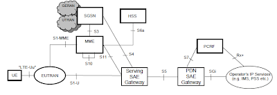
The LTE (Long-Term Evolution) network architecture is designed to provide high-speed mobile broadband with an all-IP core network and an efficient radio access network. The architecture is divided into two main components: the Evolved UMTS Terrestrial Radio Access Network (E-UTRAN) and the Evolved Packet Core (EPC). Here’s an overview of these key elements:
E-UTRAN (Evolved UMTS Terrestrial Radio Access Network): E-UTRAN is the radio access network that connects the User Equipment (UE) to the EPC. The main component of E-UTRAN is the eNodeB (evolved Node B), which handles radio communications, scheduling, mobility management, and interference management. eNodeBs communicate with each other through the X2 interface and connect to the EPC via the S1 interface.
EPC (Evolved Packet Core): The EPC is the backbone of the LTE network and is responsible for managing data routing, mobility, and network security. It consists of several key elements:
- MME (Mobility Management Entity): Manages the connection between the UE and the EPC, handling tasks like authentication, session management, and mobility management.
- SGW (Serving Gateway): Routes data between the eNodeB and the Packet Gateway (PGW). It also acts as a data forwarding point for the UE.
- PGW (Packet Gateway): Connects the LTE network to external IP networks, like the internet. It handles data packet routing, Quality of Service (QoS), and user IP address management.
- HSS (Home Subscriber Server): Contains subscriber data, including authentication information and service profiles.
- PCRF (Policy and Charging Rules Function): Manages network policies, QoS, and charging rules based on user activity and data usage.
Interfaces in LTE: The LTE network architecture includes various interfaces to ensure communication between network elements. The S1 interface connects the E-UTRAN to the EPC, while the X2 interface facilitates communication between eNodeBs for mobility and interference management.
In summary, LTE network architecture is designed to provide efficient, high-speed mobile data with an all-IP core and a flexible, scalable radio access network. The EPC and E-UTRAN work together to offer a seamless, high-performance user experience.