LTE Frame Structure
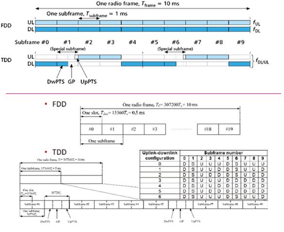
The figure below shows the LTE frame structure under Time division mode (TDD) Type 2 and Frequency Division mode (FDD) Type 1.
Differences in LTE Frame Structure
Main differences in LTE Frame Structure between the two modes are
- Frame 0 and frame 5 (always downlink in TDD)
- Frame 1 and frame 6 is always used as for synchronization in TDD
- Frame allocation for Uplink and Downlink is settable in TDD
The sampling rate in both LTE FDD and LTE TDD is the same and both technologies operate under a 1-ms sub-frame (TTI Transmission Time Interval) and 0.5us timeslot definition.
The first 3 configurations (0-2) for TDD can also be viewed as 5ms allocation due to repetition. The figure below shows a detailed relationship between rates and frame structure in LTE.
LTE Resource Block Architecture
The building block of LTE is a physical resource block (PRB) and all of the allocation of LTE physical resource blocks (PRBs) is handled by a scheduling function at the 3GPP base station (eNodeB).
What is the resource block in LTE?
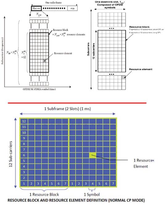
- One frame is 10ms and it consists of 10 sub-frames
- One LTE subframe is 1ms and contains 2 slots
- One slot is 0.5ms in time domain and each 0.5ms assignment can contain N resource blocks [6 < N < 110] depending on the bandwidth allocation and resource availability.
- One resource block is 0.5ms and contains 12 subcarriers for each OFDM symbol in frequency domain.
- There are 7 symbols (normal cyclic prefix) per time slot in the time domain or 6 symbols in long cyclic prefix for LTE.
LTE Resource element is the smallest unit of resource assignment and its relationship to resource block is shown as below from both a timing and frequency perspective.
Reference Signal Structure in lte resource block – What is a resource block what does it consist of?
Reference signal is the “UMTS Pilot” equivalent and it is used by UE in LTE to predict the likely coverage condition on offer for each of the eNodeB cell received. The figure below shows the locations of the reference signal within each sub-frame when transmit antennae are used by the cell.
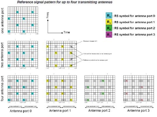
As LTE is a MIMO based technology so for lte resource block it can have more than two transmit antennae and in order to avoid reference signals from the same cell interfering with each other, different antennae will be transmitting reference signal at different time and frequency and how these are allocated are shown below.
As defined in the standard for LTE TDD operations, the channel-sounding mechanism involves the UE’s transmitting a deterministic signal that can be used by the eNodeB to estimate the UL channel from the UE.
If the LTE UL and LTE DL channels are properly calibrated, the eNodeB can then use the UL channel as an estimate of the DL channel, due to channel reciprocity thats lte resource block architecture.
What is an LTE frame structure?
In LTE, DL and UL transmissions are organized in radio frames of 10 ms each. Each frame is divided into ten subframes of equal size. The duration of each subframe is 1 ms. In addition, each subframe is further subdivided into two equal time slots, ie each slot is 0.5 ms.