The MIMO channel Matrix
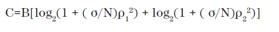
Consider for a moment in time, on the same frequency and channel modeling as a black box with durable internal components. If we add two completely different input signals is to be mixed with each other in a certain manner depending on the value of Z1 to Z4. If we send a signal training that is unique for each input and output measurement, we know how it was connected, so as to disconnect them.
All signals, data, and training will be combined in the same way, so that’s what we learned from the training signal can be applied to real data. Noise and distortion of the modulation limit, which can be used along with the ability to uncouple the outputs. The worst case would be if Z1 to Z4 are the same, when both outputs are the same and MIMO does not operate.
The best case is if the outputs are equal in magnitude and opposite in phase, when theoretically double the capacity in The MIMO channel Matrix.
Equation 1 The long-form version of the theorem of channel capacity can be written as shown in the following figure
Where,
- C = channel capacity in bits per second,
- B = occupied bandwidth in Hz, σ/N = signal to noise ratio and
- ρ = a singular value of the channel matrix
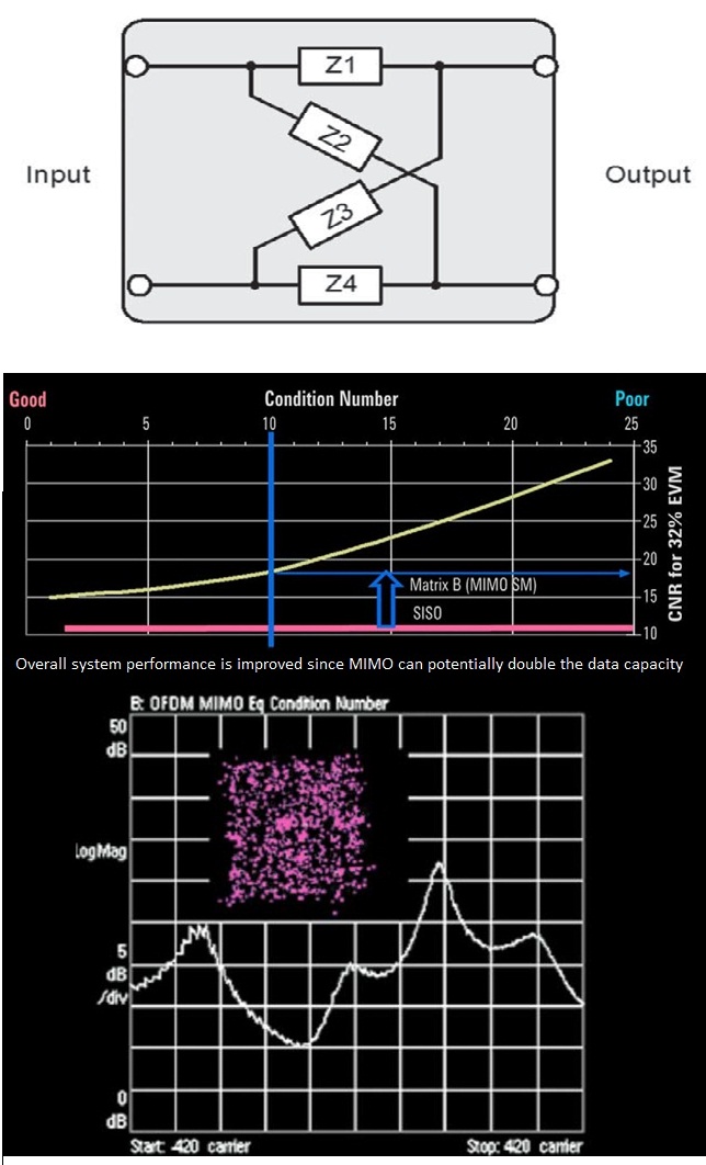
The potential in the instant system capacity increase can be derived from the relationship of singular values of the channel matrix H, also known as the condition number. The condition number of The MIMO channel Matrix can also be used to indicate the increase in SNR required recovering the MIMO signal in relation to the SISO case.
With the channel changing due to fading and trajectories multiple effects and Doppler frequency shift due to motion of phone, among others, the number of conditions to changes of constant frequency in the spectrum of RF channel, as is illustrated in the figure below.
Reference signals (or pilots) in places regular frequency at the output of each transmitter provides a way for recipients to estimate the channel coefficients. In general, each “tube” of data will not have the same performance. LTE uses feedback mechanisms known as pre-coding and make Eigen training – both forms of “closed-loop MIMO,” in the phone to request modifications to the cross-coupling of the transmitter outputs to give the best match to the MIMO channel Matrix in channel characteristics.
The MIMO Channel Matrix
In MIMO (Multiple Input Multiple Output) systems, the MIMO channel matrix is used to describe the relationship between the transmitting and receiving antennas. The matrix represents how the signal is transmitted from multiple transmit antennas and received at multiple receive antennas, factoring in the effects of fading, interference, and path loss. It plays a crucial role in determining how to process signals for optimal data transmission and reception.
Structure of the MIMO Channel Matrix:
- The MIMO channel matrix is typically denoted as H, where H is a matrix representing the channel characteristics. The matrix dimensions depend on the number of antennas at the transmitter and the receiver.
- If the transmitter has n antennas and the receiver has m antennas, then the channel matrix H is an m x n matrix. Each element of the matrix hij represents the channel gain between the j-th transmit antenna and the i-th receive antenna.
- The channel matrix H can be expressed as:
H =
    [ h11  h12 ... h1n ]
    [ h21  h22 ... h2n ]
    ...
    [ hm1  hm2 ... hmn ]
where hij represents the channel coefficient between the j-th transmit antenna and the i-th receive antenna.
Understanding MIMO Channel Characteristics:
- Channel Coefficients: The elements in the matrix hij represent the fading channel coefficients. These coefficients are typically complex numbers that model the effect of the environment, including multipath propagation, shadowing, and interference.
- Multipath Fading: In a MIMO system, signals from each transmit antenna may travel through different paths before reaching the receiver. This causes multipath fading, where the received signal can be a combination of multiple versions of the transmitted signal, each with different delays and amplitudes. The channel matrix H accounts for this phenomenon.
- Signal Decoding: At the receiver, the received signal is a combination of signals from all transmit antennas. The receiver uses the channel matrix to separate and decode the signals based on the estimated channel conditions. The matrix helps in techniques like spatial multiplexing and beamforming.
- Channel Estimation: To effectively use MIMO technology, the receiver must estimate the channel matrix H. Channel estimation is typically done by sending pilot signals from the transmitter, which are known to both the transmitter and receiver, allowing the receiver to estimate the values of the elements in the matrix.
Impact of MIMO Channel Matrix:
- Through the MIMO channel matrix, systems can employ techniques like spatial multiplexing (increasing throughput) and diversity (improving reliability) based on the estimated channel state.
- The larger the number of antennas at the transmitter and receiver, the more independent spatial streams can be transmitted, which improves system capacity and performance. For instance, in a 4×4 MIMO system, 4 independent data streams can be transmitted simultaneously.
In summary, the MIMO channel matrix H is a fundamental concept in MIMO systems, helping to model and understand how signals are transmitted and received across multiple antennas. It forms the basis for advanced techniques like spatial multiplexing, beamforming, and interference management in LTE and other wireless communication systems.