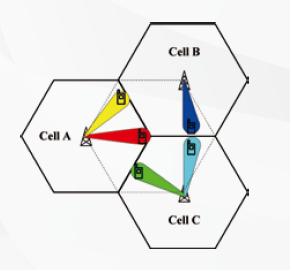
Visualization of Beam Forming in LTE
Currently, beam forming is only applicable for TDD version of LTE. The time synchronous version of LTE TDD on uplink and downlink also makes the implementation of beam forming more attractive than in LTE FDD.
Beam forming scheme is a signal processing technology that is used to direct radio transmission in a chosen angular direction. It is mainly based on an adaptive beam patterns that acts to make the strongest point of main-lobe of the system output always be toward the direction of the expected UE and hence reducing the overall interference level for the whole cell for Beam Forming in LTE
Its algorithm is highly complex and utilizes channel state information to achieve array processing SINR gain.
Channel state information that is required includes:
- Fast fading channel coefficient Beam Forming in LTE
- Direction of arrival (DoA) of signal Beam Forming in LTE
- CQI information Beam Forming in LTE
Channel state information can be obtained by different way, including:
- Feedback from receiver
- Estimation from reverse link assuming channel reciprocity (particularly true for TDD)
As it is based on a multiple transmit configuration, this feature can significantly improve downlink system throughput and coverage performance and also provide good user experience by offering higher data rates. The main drawback here is there is also the requirement of either 4 (4×4) or 8 (8×2) transmit path from the eNodeB side which could make this more expensive to implement.
There are two type of beam forming mode defined by 3GPP, Mode 7 (Rel 8) and Mode 8 (Rel 9). Mode 7 supports only single data flow so it can mainly improve coverage but Beam Forming in LTE Mode 8 can support multiplexing dual data stream as well which means it can improve both throughput and coverage.
Visualization of Beam Forming in LTE
When I talk about beamforming in LTE, it’s essentially the technique of directing the signal towards a specific user or group of users, improving signal strength and reducing interference. Think of it like focusing the light from a flashlight — instead of spreading it out in all directions, you aim it where it’s needed most. In LTE, the eNB uses multiple antennas to create directional beams, making sure the signal is stronger and more reliable where the user is located. This visualization can help you understand how beamforming optimizes coverage and capacity by focusing the radio waves rather than scattering them everywhere.