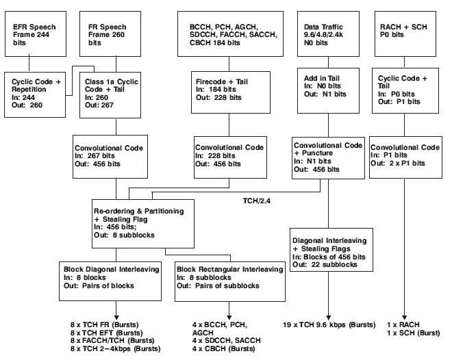
To protect the logical channels from transmission errors introduced by the radio path, many different coding schemes are used. The diagram below illustrates the coding process for speech, control and data channels; the sequence is very complex.
The coding and interleaving schemes depend on the type of logical channel to be encoded. All logical channels require some form of convolutional encoding, but since protection needs are different, the code rates may also differ.
Three coding protection schemes:
Speech Channel Encoding
The speech information for one 20 ms speech block is divided over eight GSM bursts. This ensures that if bursts are lost due to interference over the air interface the speech can still be accurately reproduced.
Common Control Channel Encoding
20 ms of information over the air will carry four bursts of control information, for example BCCH. This enables the bursts to be inserted into one TDMA multiframe.
Data Channel Encoding
The data information is spread over 22 bursts. This is because every bit of data information is very important. Therefore, when the data is reconstructed at the receiver, if a burst is lost, only a very small proportion of the 20 ms block of data will be lost. The error encoding mechanisms should then enable the missing data to be reconstructed.
Let’s Understand Each in Detail.
Speech Channel Encoding
The BTS receives transcoded speech over the A-bis interface from the BSC. At this point the speech is organized into its individual logical channels by the BTS. These logical channels of information are then channel coded before being transmitted over the air interface.
The transcoded speech information is received in frames, each containing 260 bits. The speech bits are grouped into three classes of sensitivity to errors, depending on their importance to the intelligibility of speech.
- Class 1a
Three parity bits are derived from the 50 class 1a bits. Transmission errors within these bits are catastrophic to speech intelligibility, therefore, the speech decoder is able to detect uncorrectable errors within the class 1a bits. If there are class 1a bit errors, the whole block is usually ignored.
- Class 1b
The 132 class 1b bits are not parity checked, but are fed together with the class 1a and parity bits to a convolutional encoder. Four tail bits are added which set the registers in the receiver to a known state for decoding purposes.
- Class 2
The 78 least sensitive bits are not protected at all. The resulting 456 bit block is then interleaved before being sent over the air interface.

Control Channel Encoding
The diagram below shows the principle of the error protection for the control channels. This scheme is used for all the logical signalling channels, the synchronization channel (SCH) and the random access burst (RACH). The diagram applies to SCH and RACH, but with different numbers.
When control information is received by the BTS it is received as a block of 184 bits. These bits are first protected with a cyclic block code of a class known as a Fire Code, This is particularly suitable for the detection and correction of burst errors, as it uses 40 parity bits. Before the convolutional encoding, four tail bits are added which set the registers in the receiver to a known state for decoding purposes.
The output from the encoding process for each block of 184 bits of signalling data is 456 bits, exactly the same as for speech. The resulting 456 bit block is then interleaved before being sent over the air interface.

Data Channel Encoding
The diagram below shows the principle of the error protection for the 9.6 kbit/s data channel. The other data channels at rates of 4.8 kbit/s and 2.4 kbit/s are encoded slightly differently, but the principle is the same.
Data channels are encoded using a convolutional code only. With the 9.6 kbit/s data some coded bits need to be removed (punctuated) before interleaving, so that like the speech and control channels they contain 456 bits every 20 ms.

The data traffic channels require a higher net rate (‘net rate’ means the bit rate before coding bits have been added) than their actual transmission rate. For example, the 9.6 kbit/s service will require 12 kbit/s, because status signals (such as the RS-232 DTR (Data Terminal Ready)) have to be transmitted as well.
The output from the encoding process for each block of 240 bits of data traffic is 456 bits, exactly the same as for speech and control. The resulting 456 bit block is then interleaved before being sent over the air interface.